|
I have a Colchester 13x24 "roundtop" lathe with a metric leadscrew for which I
wanted to make a threading dial.
In order for it to work for the full range of thread cutting it needs to have
five different gears: 16, 18, 20, 21 and 22 teeth.
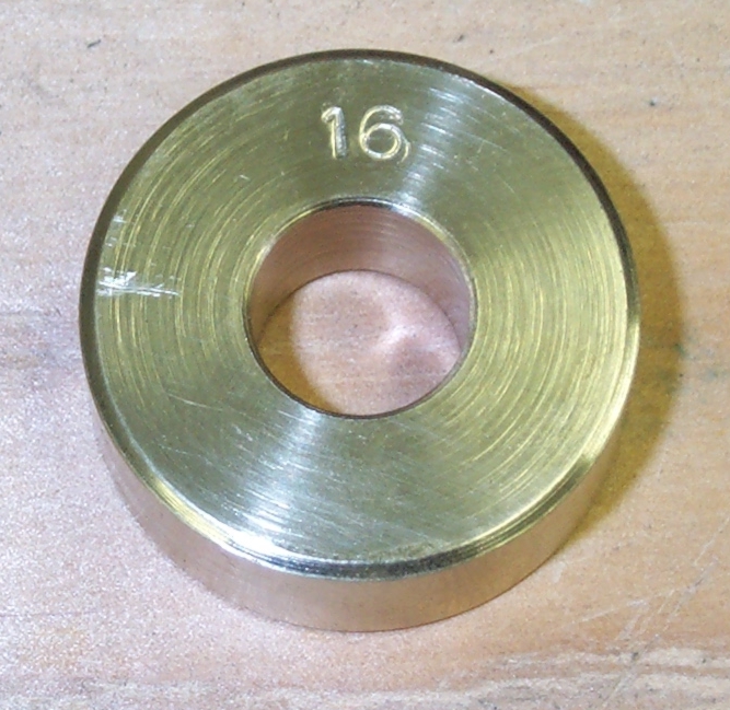
I have a 16T gear that mates with the leadscrew from a rapid threading
attachment so I used it as a model from which to make
the new gears.
|
|
The leadscrew is 1.125" O.D. and 6mm pitch acme thread.
I calculated that the helix angle of the leadscrew is 4.3 degrees which
compares favorably with the measured angle of the teeth on the existing gear.
I chose to make the gears on my Atlas 7" shaper so I ground a 1/4" HSS bit to
match the profile of the slot between the teeth on the existing gear.
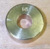
I turned the gear blanks from aluminum bronze. This one, for the 16T gear, is
1.280 in diameter and .500 thick with a .500 center hole.
|
|
|
Next I went about setting up the shaper to make the cuts. I first made an
arbor using 3/4" drill rod to hold the gear during cutting. Since I couldn't use
the tailstock due to space limitations, I needed to hold the arbor in a chuck
with as little protrusion as possible. Because vertical space was so tight,
I first tried to cut on the side of the gear blank, having the toolholder in
the 3 o'clock position when viewed from the front. This arrangement allowed too
much flex in the toolholder and/or the clapper and as a result the cutter would
dig in terribly.
|
|
I concluded that I needed to switch to cutting on top with the bit projecting
downward from the toolpost as is normally done. I could just barely get this to work for the 16
tooth gear that I started with but I could see that it wouldn't work at all for
the larger gears. In this configuration the standard shaper toolpost ended up
being too large (it would hit the chuck before the stroke was completed) so I
made a "stubby" toolpost that would give me the necessary clearance.
I had already cut the bit down from its original length for use in a
standard toolholder and it was, therefore, too short to clamp directly in the
toolpost. Not wanting to grind another bit, I made a bit holder that could be
clamped in the new toolpost to give me minimal overhang. The square hole in the
bit holder was cut using a 1/4" square broach. More detailed information on the
toolpost and toolholders may be found here.
|
|
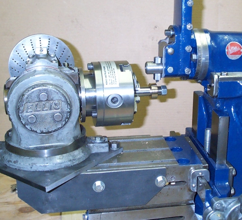
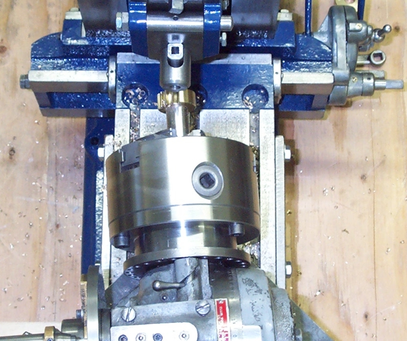
Here are two views of the setup and a closeup of the cutter and blank. The table
is as low as it will go. With the modified tooling, the compound still has good
engagement on its dovetails. Note in the overhead view that the dividing head is
angled slightly off the centerline of the shaper stroke.
This gives the teeth the proper angle (4.3 degrees) for meshing with the leadscrew.
|
|
|
|
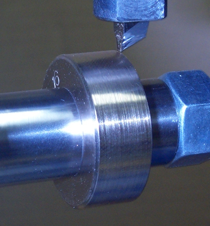
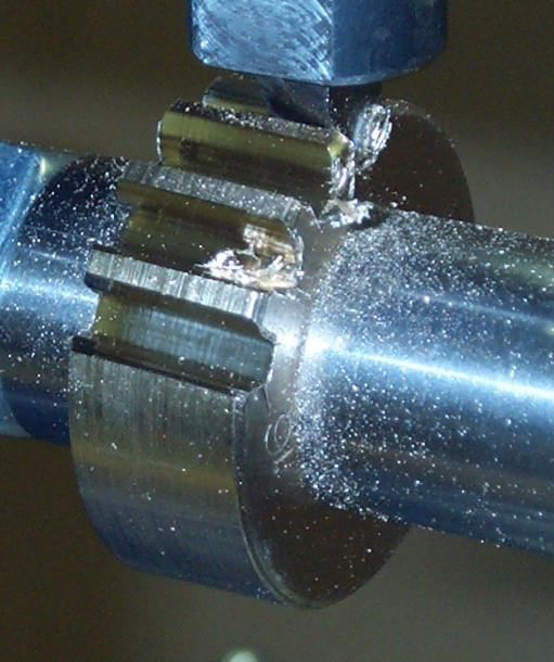
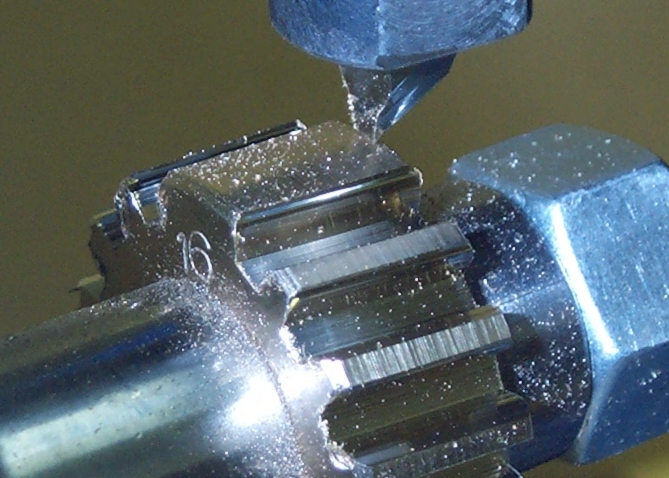
Here are a couple of pictures of the cutting process. I was able to downfeed
the tool .003 to .005 for each stroke and get a fairly smooth cut. The total
downfeed was about .110. Each tooth took a bit less than 2.5 minutes to complete.
|
|
|
|
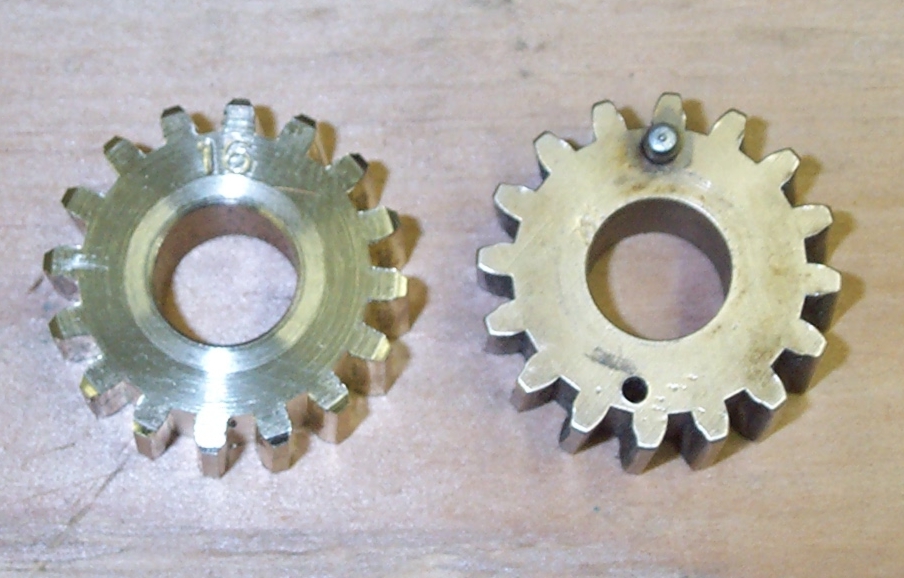
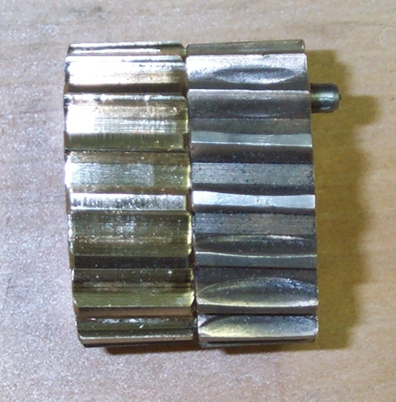
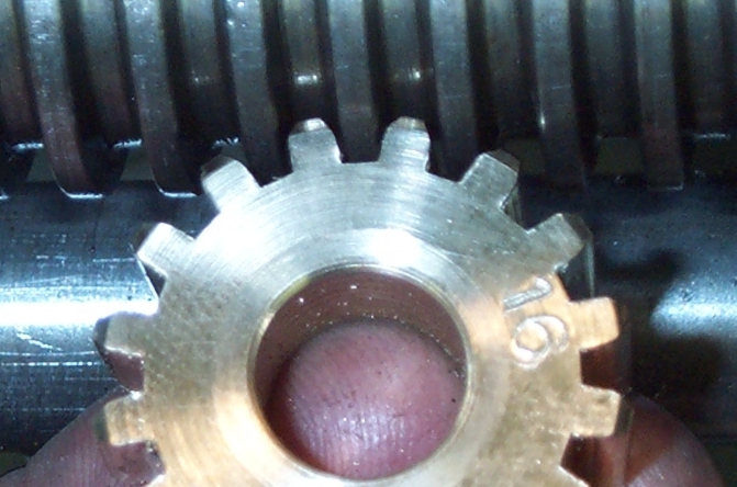
Finally, some pictures of the completed gear comparing it with the existing gear and
one showing the mesh with the leadscrew.
|
|
|