|
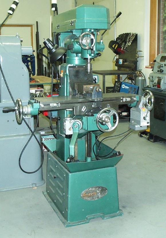
The Grizzly G1004 is a knee mill with an 8x30 table which is no longer being made.
My previous mill was a smaller import knee mill with a 6x24 table so this is a nice
step up for me. I purchased the machine from a fellow locally that had used it for about a
year before he got a good deal on a 9x42 Bridgeport.
This page describes some modifications that I have made to the machine.
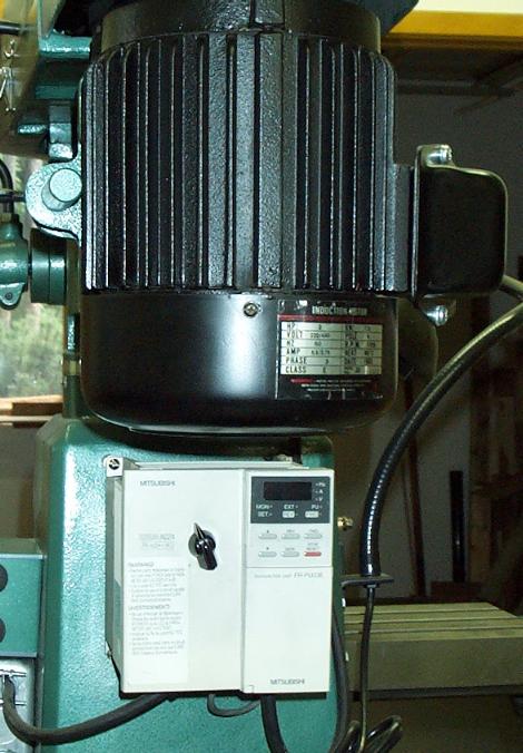
When I got the mill it had the original factory single phase dual-voltage motor on it.
One of the first things that I did was to convert it to three phase and install a VFD on it.
I was able to pick up locally an import three phase 2 HP motor, one that someone had likely
removed to convert a machine to single phase. About the same time I got an excellent deal
on a Mitsubishi FR-A024-1.5K variable frequency drive that is single-phase compatible.
This 2HP VFD is the type that requires a separate keypad plug-in to program it so I had to purchase
one of those through a local distributor.
Together, the drive and keypad were less than $100 including shipping.
A picture of the VFD mounted on the back of the mill may be viewed here.
I installed a speed control potentiometer in the VFD itself and then wired the mill's existing
control switch to the VFD's control terminals.
This setup makes the VFD very convenient to use.
A second modification that I made was to add an X-axis powerfeed unit.
I picked up an import 150 inch-lb unit on eBay that was originally sold through Harbor Freight.
The same design is marketed under a variety of different names and is available from various sources.
The powerfeed is designed, supposedly, to be installed on a Bridgeport.
The supplied adapter plate, drive gear and bushings couldn't be used on the Grizzly mill
directly but I was able to make some new parts and modify the existing parts to install the drive.
The two pictures below show closeup views of the finished installation.
The following pictures and text describe, generally, the process to install the drive.
|
|
|
|
|
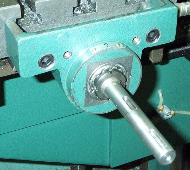
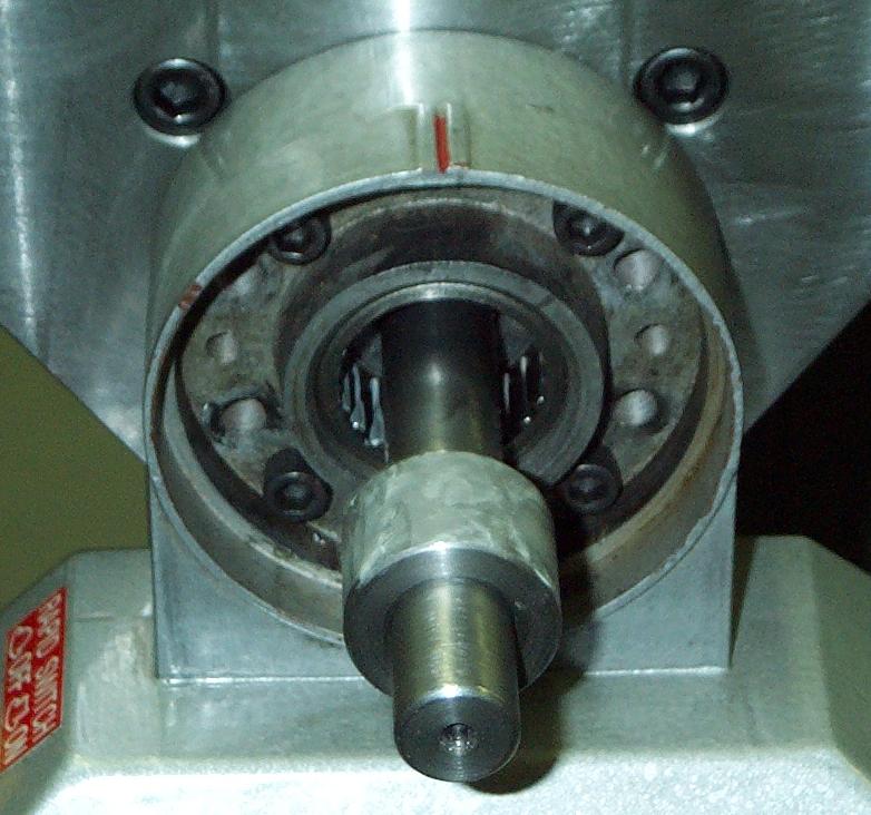
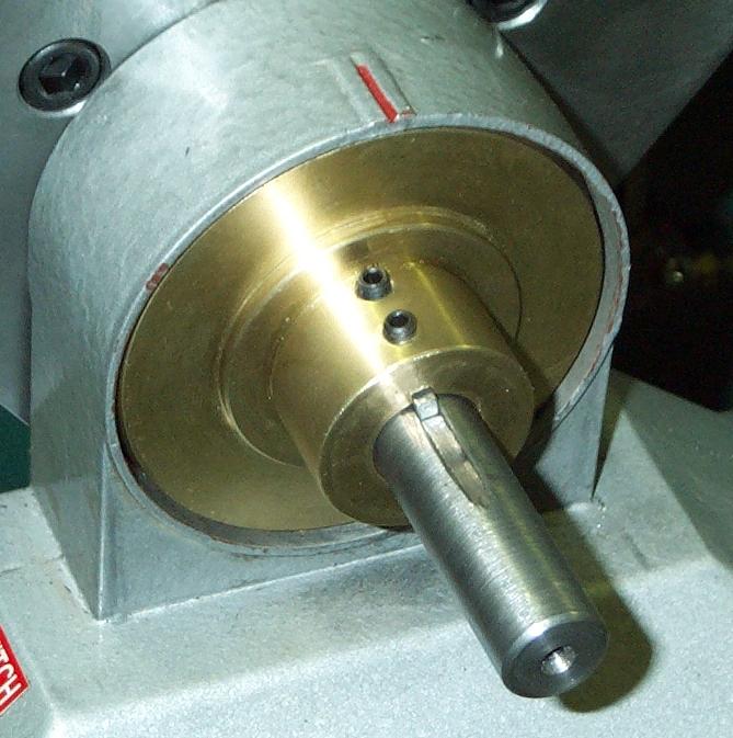
This picture with the right side handwheel removed shows the leadscrew extension.
The innermost keyway is the original keyway for the handwheel while the outer one is
the new handwheel keyway.
The leadscrew was removed from the mill and was drilled/reamed for a 0.250 pin made from
drill rod. A 2" extension piece with a diameter slightly larger than the leadscrew
was similarly drilled and the mating ends of the leadscrew and extension were beveled
in preparation for welding.
The extension and pin were pressed into the leadscrew and then the assembly was welded
after which the weld bead and extension were turned down to the same diameter as the
leadscrew.
|
|
|
|
|
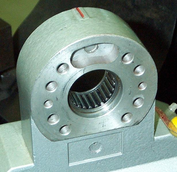
The bearing flange in the picture above was originally attached to the end of the table with two 6 mm screws.
I was concerned about the load bearing capability of these screws so I re-drilled and tapped
the table and drilled the flange to allow 3/8-16 screws to be used. Also note that the
flange has been drilled and tapped for 5/16-18 screws for attaching the adapter plate (seen below).
|
|
|
|
|
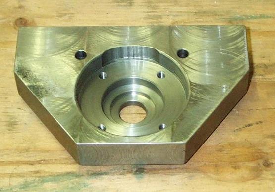
This picture shows the back side of the adapter plate which has been bored to clear
the protrusion on the bearing flange.
The plate was made from two half inch plates welded together since I didn't have any 1 inch
plate stock on hand.
The recess for the bearing flange is slightly over a half inch deep.
|
|
|
|
|
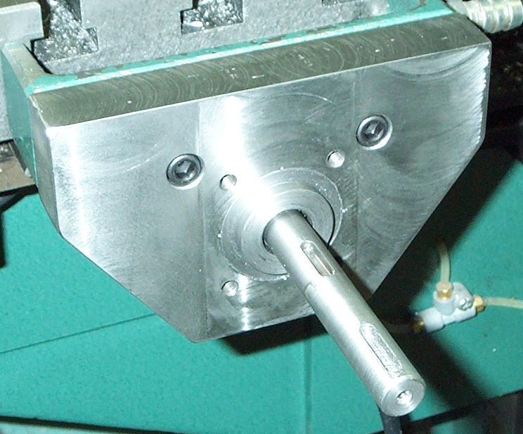
Here you can see the adapter plate installed.
There is a small step bushing on the adapter that was machined to fit a recess in the back of the
power feed unit.
The step bushing was pressed into a matching bore on the adapter plate with four center
punches around the perimeter to tighten it up.
|
|
|
|
|
This is a view of the side of power feed that mounts toward the adapter.
The bore holding the needle bearing fits over the step bushing on the adapter plate
in order to maintain axial alignment.
|
|
|
|
|
Here the power feed unit is mounted on the adapter plate with the bushing ready to be installed.
The power feed's four attachment screws were tightened before the two screws holding the adapter
plate to the mill table in order to maintain axial alignment.
|
|
|
|
|
This picture shows the bushing fully installed.
The bushing's O.D. was machined to fit the needle bearing and the I.D. to have a slip fit on the leadscrew.
The bushing that was supplied with the power feed unit had an I.D. too large for the
leadscrew.
This is odd because the unit claims to be for mills with a 5/8" leadscrew and the Grizzly's
leadscrew is 0.626".
|
|
|
|
|
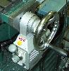
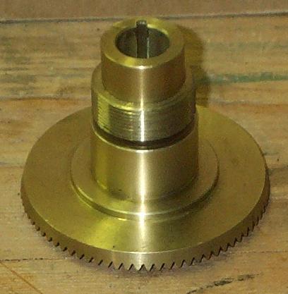
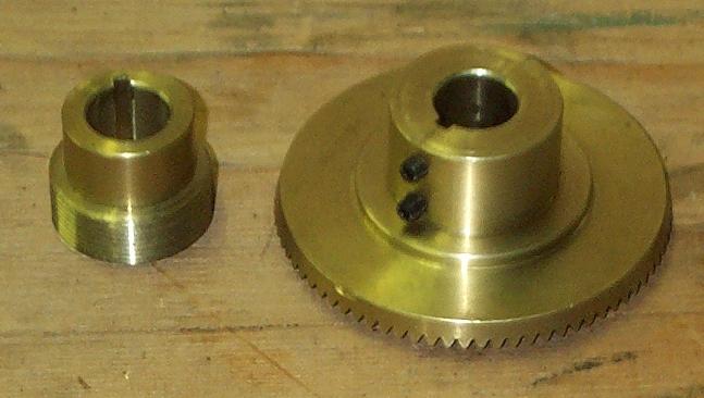
These two pictures show the bevel gear that is driven by the power feed unit and, in turn,
drives the leadscrew.
It had to be modified as shown in the second picture to fit the application.
Firstly, the threaded portion was cut off because it was not needed and with it the hub
was too long - the handwheel wouldn't fit up to the power feed unit.
Secondly, it had to be bored out slightly to accommodate the mill's leadscrew.
Finally, the keyway was enlarged to permit the use of a 1/8" square key and the hub
was drilled and tapped for two 8-32 set screws.
|
|
|
|
|
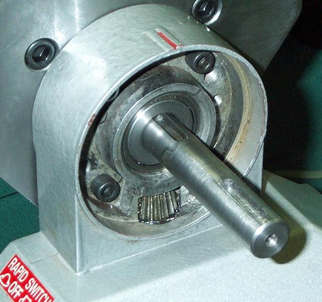
This picture shows the bevel gear installed.
The keyway for the bevel gear in the leadscrew had to be cut through the weld where the leadscrew extension is attached.
I didn't anneal the weld area and it ended up being fairly hard.
To get through the hard portion, I ended up using a 4" grinder with a cutoff wheel.
You can see a couple of places where I ground more than I really wanted.
The result isn't pretty but it is serviceable.
|
|
|
|
|
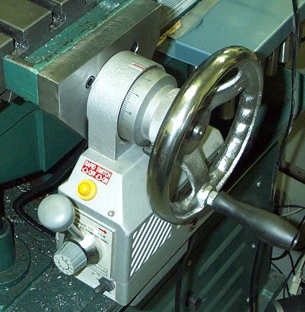
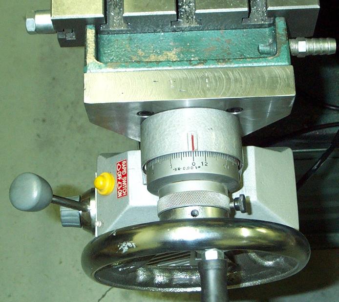
Finally, the handwheel is installed completing the assembly.
The graduated dial is slightly smaller than the diameter of the bevel gear.
I have considered making a disk to fit between the bevel gear and the dial to keep
out swarf and other debris.
For now, I'll keep an eye it and decide later if it's necessary.
|
|
|
|
|
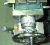
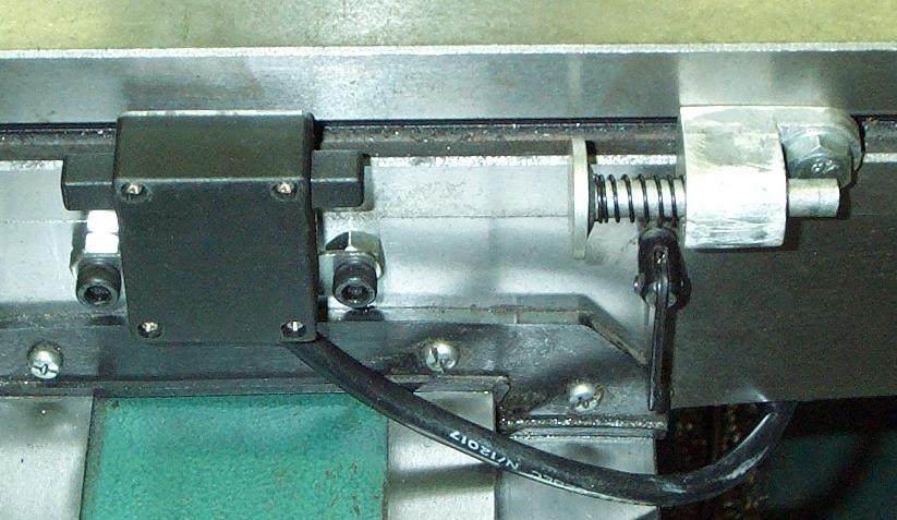
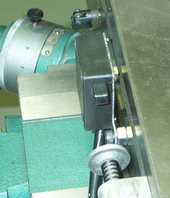
These two pictures show how the limit switch was mounted.
The bracket provided with the power feed unit had a bend in it making it unsuitable for this application.
I could have flattened it but I chose instead to make a bracket from sheet steel that holds
the switch in position so it can be activated by the spring loaded stops.
There are four 3 mm screws holding the limit switch housing to the bracket.
The spacers employed are 5/16" nuts which are slightly shorter than what is needed; the switch
plungers are not quite centered on the spring stops.
These work fine but I may later make some slightly longer spacers if it appears to be necessary.
|
|
|
|